Hardware
Motor
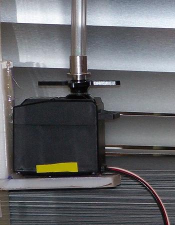
Our final mechanical system is shown here. After researching and experimenting with various solutions, we found a simple solution in the stockrooms. Using what looks to be a button casing for a game controller, a long screw from the MechE stockroom as well as a metallic clasp, we were able to make a simple yet effective system that holds the end of the blind rod and turns the rod without causing any slipping.
The button casing screws into the servo arms and the wand slides easily into it. After clamping the sides of the casing with a small metal clasp, the wand is secured.
Circuit
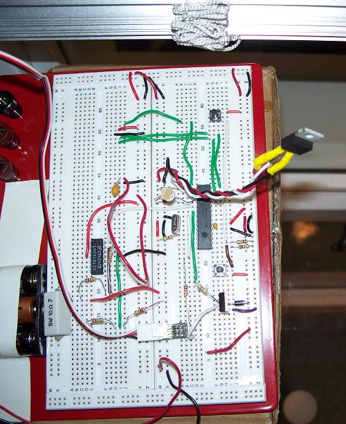
The main component of the circuit is the PIC, which keeps track of the timer, takes in signals from temperature sensor, light sensor and regulate the position of the motor based on those two and the transistor. Another components of the circuit is the op-amp, which send a signal to the PIC when the servo motor draws more current than usual, which happens when the system reaches to the end of the blinds. A circuit diagram of the PIC circuit without the op-amp is shown below.

By incorporating the op-amp circuit, we hope to determine from the increase in current when the blinds are completely closed. we also experimented with incorporating a tilt sensor to determine when the blinds were fully open. However, programming the PIC to receive input from op-amp and the tilt sensor, then implementing the needed action from the motor proved to be a challenge that will need to be investigated further.
Total cost of producing a prototype is shown below:
| Item | Quantity | Cost (Total) |
| Servo (STD53) | 1 | $10.00 |
| Temperature Sensor (LM35DT) | 1 | $3.00 |
| Light Sensor | 1 | $0.60 |
| Transistor (IRF1104) | 1 | $5.00 |
| Diode | 1 | $1.00 |
| Battery holder | 1 | $1.00 |
| Pic (18F2455) | 1 | $4.00 |
| Resistors | 10 | $0.10 |
| Capacitor | 1 | $0.25 |
| Breadboard | 1 | $10.00 |
| $34.95 |