Designing a Liquid Crystal Display
Team Members: Kevin Cheng, Chujiao Ma, Heena Mutha
Fall 2008
Team Members: Kevin Cheng, Chujiao Ma, Heena Mutha
Fall 2008
Differential Scanning Calorimeter
(DSC)
Having
observed a qualitative phase transition under the microscope, we decided to
quantify the phase transition using the DSC. We found an endothermic and
exothermic peak at 33.7 ⁰C, indicating a first-order phase transition,
similar to the 35 ⁰C given in the literature [2]. We also observed
another endothermic peak at 40 ⁰C, which might be related to overcoming
the energy associated with the surface pinning, which was suggested in the
subsequent DSC test.
For the
second DSC test, we scratched the pan with sandpaper to create a surface
treatment. The large endothermic/exothermic peak continued to occur at 33.7
deg C, but the other endothermic dip occurred at 47.0 deg C. The surface
treatment caused a temperature shift of this peak by 6 ⁰C, suggesting
that the liquid crystal has a bulk transition at 33.7 ⁰C, but does not
reach a completely nematic state until enough energy is available to overcome
the surface energetic.
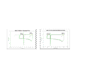
Figure 4.
DSC of 5CB in untreated and scratched pans. Both experiments exhibit a
hysteresis loop as the sample is thermally cycled. The scratched pan had an
endothermic peak 7 ⁰C higher than the untreated pan. The untreated pan
5CB sample’s mass was 2.3 mg, and was cycled 6 times from 28 ⁰C to 42
⁰C. In the scratched surface experiment, the sample’s mass was 3.6 mg,
and was cycled 6 times from 28 ⁰C to 52 ⁰C.
We
found the latent heat of the first reaction to be 6.02 J/g and the second as
5.403 J/g. The literature value for the
latent heat of formation during this phase transition is .8 kJ/mole [2], or
3.16 J/g, an error of 70-90 percent! This indicates that the DSC is not calibrated to make
quantitative claims on the latent heats of the reactions observed.
References:
[1] Collings, P. 1990. Liquid
Crystals: Nature’s Delicate Phase of Matter. Princeton, NJ: Princeton
University
[2] Chandrasekhar, S. 1992. Liquid
Crystals (2nd ed.). Cambridge,UK: Cambridge University Press.
[3] Chaikin, P.M, Lubensky, T.C.
1995. Principles of Condensed Matter Physics. New York, NY: Cambridge
University Press
[4] Daoud, M. and Williams, C. 1999. Soft Matter Physics. New York, NY:
Springer-Verlag.
[5] Murphy, D. 2001. Fundamentals of
Light Microscopy. New York, NY: John Wiley and Sons
[6] Wolfson, R. and Pasachoff, J.
1998. Physics-for Scientists and Engineers (3rd Ed.). Cambridge, MA:
Addison-Wesley
[7]
http://walba.colorado.edu/2003_Chem_6321/5cb%20solution/5CB.htm

Typical Assembly of a Liquid Crystal Display
The
construction of the LCD utilizes the nematic properties of the liquid crystal,
and the capabilities of applying external energies to alter the orientation of
the liquid crystal. These are the
critical properties that make it work [1], shown in the figure below:
2.
The glass plates are coated with a conductive material, such as Indium Tin
Oxide (ITO) to create electrodes.
3. The glass plates are separated by thin film
spacers (5-25 um) in order to create the required electric field with reasonable
voltages.
4.
Polarizers on either side, aligned with the surface treatment, allow for the
light to be absorbed and transmitted
as desired.
Figure 5. Typical structure of a liquid crystal
display.
To determine how temperature affects 5CB, we heated the
crystals and observed it between crossed polarizers. The liquid crystals are
slightly aligned with the natural surface of the slides, which allows light to
go through and produce the silver color that we observed as shown in the
figure below. As temperature increases, the liquid crystal enters the
isotropic phase and becomes disordered. When the directors are completely
randomized, the linearized light is not altered as it passes through the
liquid crystal and is therefore absorbed by the polarizers.
The transition happened between 35 to 36 ⁰C. This
is in-line with scientific studies that have characterized the phase
transition from nematic to isotropic at 35 ⁰C [2]. As we switch between
the transitions, the surface alignment changes and there are significant
fluctuations as the liquid crystal goes between nematic and isotropic.
Phase Transition
Introduction
In 1888,
Friedrich Reinitzer discovered liquid crystals when he was melting cholesterol
benzoate crystal and observed two distinct liquid phases [4]. Liquid crystal
molecules in the nematic phase are randomly distributed but are locally
aligned along the same direction, or director. The director has no intrinsic preferred orientation, meaning it
can be influenced by many external perturbations, such as electric field, the
surfaces in contact with the liquid crystals, and thermal energies [4]. Liquid
Crystal Displays (LCD) technologies rely on these effects. In order to
characterize the liquid crystal, 5CB, our team studied the effects of thermal,
surface, and electrical influences by synthesizing a LCD.
Conclusions
By varying
thermal, electrical, and surface parameters, we ultimately synthesized a
working LCD pixel. We found that the crossed surface treatment is integral to
creating a working pixel, as the twisted nematic is required for the
transmittance of light through crossed polarizers. Also because a relatively
high electrical energy, 1.185 V/um, is required to overcome the surface
treatment, the space between the glass plates needs to be very small. The cell
that only had a 30 um between the electrodes successfully created a pixel, but
the cells with gaps > 100 um were too large to create an electric field
that would be strong enough to change the crystal alignment, given the
available equipment.
Figure 9: DSC of 5CB in polyamide
tape and PVA treated pans. The sample masses for each experiment were 2.4 and
3.0 mg, respectively. Both samples were cycled 6 times from 28 ⁰C to 52
⁰C.
Surface Pinning Strength
The success of LCD synthesis using a
PVA surface treatment led us to the question: does a PVA surface treatment take less energy to overcome than the
polyamide tape treatment? We used the
DSC to investigate this possibility.
The endothermic dip occurred at 49.0
⁰C for both treatments, which may be indicative that both surface treatments pin the liquid crystal with similar
strength. Further experimentation is necessary
to confirm this hypothesis.
Given the results of the DSC and
electric field calculations, we conclude that the cell gap size is what influenced the success of the LCD.
We tested
the transmissivity of the liquid crystal slides using the spectrophotometer to
get an idea of the efficiency of the LCD. As expected, the slide is more
transmissive under crossed polarizers than when heated [4]. As shown in the
figure below, the transmissivity drops off at shorter wavelengths, or the UV
spectrum. The results with crossed polarizers is even across the spectrum, so
the difference in transmissivity is due to the glass slides and the polyamide,
both of which are generally UV resistant. As mentioned in the polarizers
section, we expect the transmission of the LCD with crossed polarizers to be
less than 25% of the original incident light.

Characteristics
of Liquid Crystal
Figure 2: Nematic to isotropic phase
transition. The transition happens between 35 to 36 degrees.
Figure 3: Isotropic to
nematic phase transition. The image
above is from 36 to 35 degrees.

Another
characteristic essential to liquid crystals in a LCD is the ability to align
with an electric field. To confirm this, we placed 5CB between two electrodes
spaced 50 microns apart from each other. At 14.2 volts, we observed the
effects shown in figure 4, where there are many Maltese crosses scattered
throughout the slide. Maltese crosses are formed when the director in an area
diverges from a point in two dimensions [4]. Therefore, the Maltese crosses
seen are formed when current flows between the two electrodes, which creates a
radial electric field. Although this was not the desired electric response for
a LCD, it does prove that liquid crystals do align with an electric field.
Electrical Effect
Figure 4: Electrical effect on ITO
slides at 14.2 V.
Figure 6. PVA slides with cross
surface treatment viewed under cross polarizers. Polyamide slides with
parallel surface treatment viewed under cross polarizers. Polyamide slides
with crossed surface treatment viewed under cross polarizers.
Figure 7. The transmission graph of
liquid crystal with crossed surface treatment.
We used a typical
parallel-plate capacitor configuration to calculate the electric field across
the liquid crystal, taking into account the dielectric constant of our polymer
surface treatment as shown in the figure below:
In a standard parallel-plate capacitor problem with no
dielectric in the middle we have
[6]. With liquid crystal as the dielectric between plates, we have a
new electric field: .
Because we have different mediums with different dielectrics, we sum the
effects, to find the voltage:
This implies that a greater
dielectric constant for the polymer reduces the field. We found that the dielectric constants of polyamide tape, polyvinyl
alcohol, and liquid crystal are 3.4,
2.0, and 18 respectively [7].
Since the liquid crystal responded at the critical voltage of 75 V, for PVA is ________. Using this electric field, we calculate that the
polyamide tape chamber
(slide 2) would have needed 510.8 V. This implies that the spacing was very
critical to the success
of the LCD.
Polarizing
filters linearize light. Typically, light vibrates in all directions.
Polarizers only allow light vibrating in the plane parallel to it to pass [5].
If the second polarizer, the analyzer, is parallel to the first polarizer,
then the light that passes through the polarizer will also pass through the
analyzer. If the analyzer is oriented perpendicular to the polarizer, then the
light passing through the polarizer is perpendicular to direction of the
analyzer. Therefore it cannot pass through, and the area appears dark [5].

Figure 1: a) illustration of light
passing through a vertical polarizer.
b) illustration of two parallel polarizers on top of each other. c) illustration of two crossed polarizers on
top of each other.[5]


Having studied a variety of liquid
crystal characteristics, we built slide 1, using the surface treatment and cell width as given in the table above.
The first slide failed to react to an applied electric field. Since the width of the cell might be a
factor in this failure, we reduced the chamber size to 10 μm. Also, the surface treatment might be
too strong, so we built a cell with PVA and another with the polyamide tape. Out of the three cells,
only the third with a distance of 30 μm
showed any response to
an electric field.
When we applied a voltage to slide
3, we can visibly see that the light intensity decreases. Although it does not uniformly align the director and go
perfectly dark, the fact that the light intensity is reduced proves that the electric field is
moving the director from its surface pinning. When the voltage is turned off, the liquid crystals
return to the twisted nematic state. We first start seeing a response at 21.4 V, but with an increased
electric field, the effects are more intense,
widespread and uniform. By 75V we achieve the best response possible given our
equipment.
In order to narrow down why slide 3
worked and slide 2 did not, we decided to investigate the strength of the surface treatment using the DSC, and
also determine the electric field needed to create a response.
Figure 8: Electrical response of LCD
pixel at 0 V (left), 21.4 V (middle), and 75 V (right).
Characteristics of LCD

Building of
the Cell

The liquid crystals
take on the alignment of the surfaces they are in contact with [3]. To
investigate the effects of surface treatments on the LCD, we made slides with
the two materials available to us, Kapton© polyamide tape
and polyvinyl alcohol (PVA), which are typically used to make LCDs [1]. We
made the PVA and polyamide slides with a crossed surface alignment, which
twists the liquid crystals. Then we also made polyamide slides with parallel
surface alignment.
As shown below, the PVA
and polyamide cross surface treated slides transmit light between crossed
polarizers. The slides with parallel surface treatment do not alter the light
in any way. When the top and bottom surfaces have different alignment, the liquid
crystal aligns with both surface while twists in the middle to make a smooth
transition between the plates. This twist allows light to go through crossed
polarizers while blocking light when between parallel polarizers [4].
The slides with PVA
visually transmits light just as effectively as the slides with polyamide
tape. However, we decided to proceed with polyamide tape in our LCD synthesis
because it is easier to apply.

Ep= σ/kpε0
Egap=σ/klcε0
Ep= σ/kpε0
} spacer thickness
}
cell thickness
} spacer thickness


